| PRODUCT |
|
|
Changzhou Dacan Electronic Co., Ltd Mob: +86(0)13915077376 Tel: +86-519-85606622 Fax: +86-519-85607968 E_mail: sales@czdacan.com Web: www.oudz.cn |
Digital active power meters are applied in the electric power grid, automatic control system, the main usage is to measure active power in the electric power grid, in accordance with the additional functions, the meters can be divided into 3 series digital display meters: X, K, S series.
X Series intelligent digital display active power meters are through AC sampling directly, and using software to measure the active power value, they are digital electric capacity meters that display directly by the meter head digital diode (LED).
K Series intelligent digital display active power meters based on the X-series, have an increase of one way analog transmission output (4-20mA, etc.) and one way RS485 communication interface output(using the Modbus-RTU protocol), in order to facilitate digital display meters in the group networking.
S series digital alarm monitoring control meters are based on the X-series, to increase two-way relay alarm output function (to achieve “the remote control function”).
Specific technical standard please refer to general specification of digital display meters.
The Products meet the standard of GB/T22264.1-2008, GB/T 13978-2008.
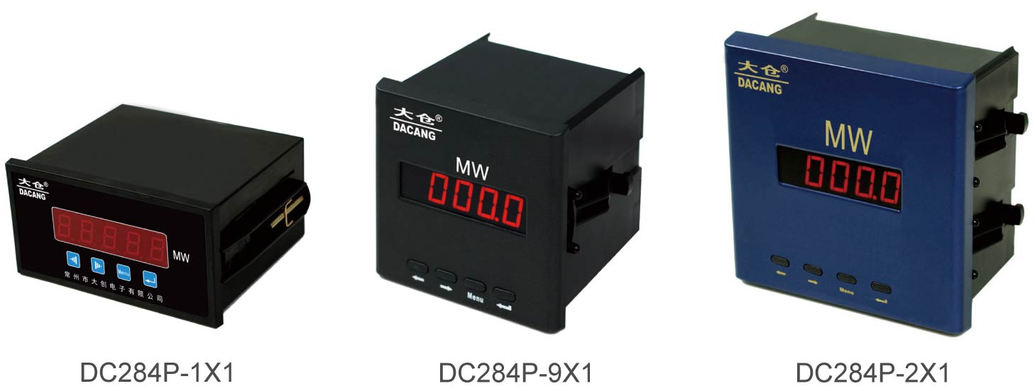
2. Typical Product Pictures

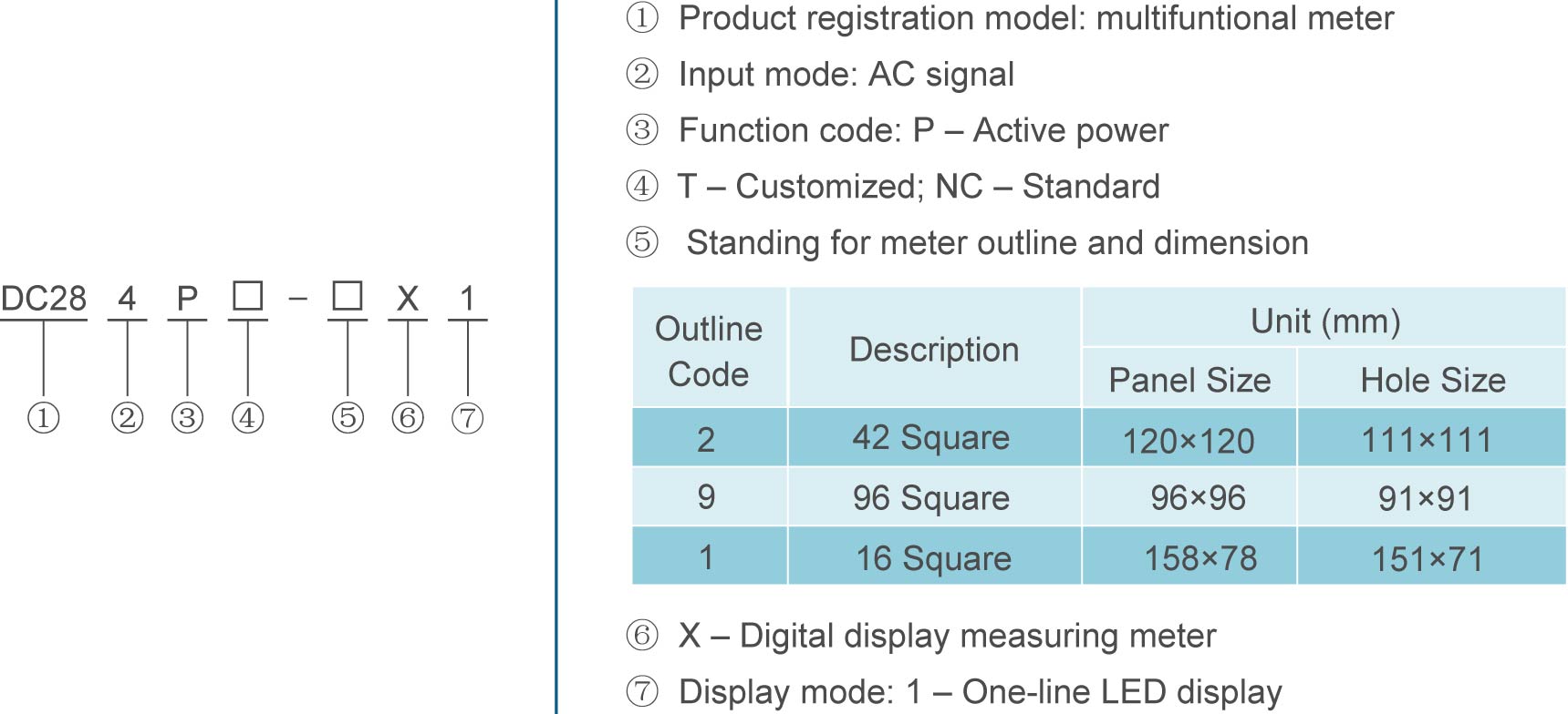
3. Models and Meaning of Products

4. Products Models
|
Model Product function |
DC284P-2X1 |
DC284P-9X1 |
DC284P-1X1 |
|
|
Real-time measurement |
Three-phase voltage |
- |
- |
- |
|
Three-phase current |
- |
- |
- |
|
|
Active power |
√ |
√ |
√ |
|
|
Reactive power |
- |
- |
- |
|
|
Power factor |
- |
- |
- |
|
|
Frequency |
- |
- |
- |
|
|
Analog output |
AO (DC4-20mA) |
- |
- |
- |
|
Relay output |
DO (AC250V/5A , Remote/Alarm |
- |
- |
- |
|
On-off input |
DI (Passive stem node) |
- |
- |
- |
|
Communication interface |
RS485, Modbus-RTU |
- |
- |
- |
|
Display mode |
One-line LED |
|||
|
Panel size (mm) |
120x120 |
96x96 |
158x78 |
|
|
Hole size (mm) |
111x111 |
91x91 |
151x71 |
|
|
Installation mode |
Panel Mounting |
|||
|
Remark: 1) “√” means the model has the function. 2) “ - “ means the model doesn’t have such function. 3) The number means channel, for example: 2 means the model has the function with 2 channels. |
||||
5. Technical Specifications
|
Parameters |
|||
|
Precision grade |
Electric capacity metering: active electric energy: 0.5 class, reactive electric energy grade:1.0, transmission output grade 0.5 |
||
|
Display mode |
LED display |
||
|
Input signal |
Measurement network |
Three-phase four-wire V34/Three-phase three-wire V33 |
|
|
Voltage |
Rated voltage |
AC100V, AC400V |
|
|
Excess load |
Continuance: 1.2 times; Instantaneous: 2 times (10s) |
||
|
Power consumption |
<0.6VA (each phase) |
||
|
Impedance |
>200kΩ |
||
|
Current |
Rated current |
AC5A / AC1A |
|
|
Excess load |
Continuance: 1.2 times; Instantaneous: 10 times (5s) |
||
|
Power consumption |
<0.4VA (each phase) |
||
|
Impedance |
<20mΩ |
||
|
Frequency |
45-65Hz (0.01Hz) |
||
|
Electric energy |
Bi-directional Active/Reactive electric energy metering |
||
|
Power supply |
Working scope |
AC/DC 85-264V |
|
|
Power consumption |
<5VA |
||
|
Function modules |
Electric energy pulse |
Passive optical coupler collector output |
|
|
Communication interface |
1-way RS485 communication interface, Modbus-RTU Protocol |
||
|
Transmission output |
0-20mA/4-20mA/0-5V/1-5V transmission output, programmable to setting transmission items and relative output data. |
||
|
Security |
Insulation resistance |
≥100MΩ |
|
|
Resist pressure |
Input voltage>1kV, Input and output>2kV, Power supply and output>2kV |
||
|
Work environment |
Temperature |
-10℃~55℃ |
|
|
Relative humidity |
≤93%RH |
||
|
Altitude |
Non-corrosive gas forum, Altitude ≤2500m |
||
|
storage environment |
Temperature |
-20℃~75℃ |
|
|
Relative humidity |
≤93%RH |
||
6. Outline Dimension

DC284P-2X1

DC284P-9X1

DC284P-1X1
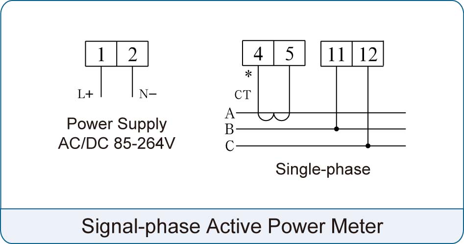
7. Typical Signal Input Wiring Diagram

Note: the above diagram is only for reference, the actual parameters in the factory shall prevail.
Wiring Instruction:
l Input voltage cannot exceed rated input voltage (100V or 400V), otherwise should consider using PT, in order to make maintenance easily, advice to use connector bar.
l Standard rated input current is 5A or 1A, if in the situation of more than 5A, should use exterior CT. If using CT with other meters, wiring method should be series connection, before removing the wire of input current, make sure that cut off CT one circuit or Short sub-secondary circuit in advance, in order to make maintenance easily, advice to use connector bar.
l Make sure input voltage is correspond with input current, phase no. consistent, directions are consistent, otherwise the value and the symbol of power and electric energy will be wrong.
l The meter can work in three-phase four-wire or three-phase three-wire mode, the users should select the appropriate wiring way based on the site situation. Usually under the situation without center line, use three-phase three-wire mode, while three-phase four-wire mode under the situation of center line. Please pay attention that onsite wiring mode must be consistent with the wiring default setting of the meter, otherwise the data of measured by meters will be incorrect.
8. Ordering Example
When order please specify the required models, power supply, signal input, the transformation ratio, display requirements and relative content. Accuracy class, the default is Class 0.5. For example, if need Class 0.2, please specify when ordering.
l Model: DC284P-9X1
l Power supply: AC 220V
l Signal Input: 100A/5A, 10kA/100V
l Other: other factory pre-sets (if no indication when ordering, ex-factory products will be delivered in accordance with the default setting).

